LCR Resonance Calculator
This calculator determines the resonant frequency, angular frequency, reactance, quality factor (Q), bandwidth (BW), and half-power cutoff frequencies ($f_1$ and $f_2$) for both series and parallel LCR/RLC circuits based on resistance (R), inductance (L), and capacitance (C).
Formulas
About LCR Resonance
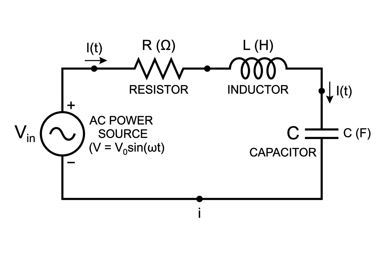
Resonance in LCR circuits occurs when inductive reactance ($X_L$) equals capacitive reactance ($X_C$).
- In a **Series RLC circuit**, the total impedance drops to a minimum (equal to R) at resonance, maximizing the current flow through the circuit.
- In a **Parallel RLC circuit**, the total impedance rises to a maximum at resonance, minimizing the line current drawn from the source.
A higher Q factor corresponds to a narrower bandwidth (sharper peak).
Input Parameters
Calculation Results
Enter parameters and click "Calculate" to show results.